Links
Tags
Trialling Claude Code as a Sceptical Developer
If you're already familiar with Claude Code or any of the other agentic AI coding tools it competes with, then you can probably skip this post. In the face of daily updates of new tools, new competitors and lingo to get across - this tries to keep it simple with just enough depth on my very short experience with Claude Code (Pro Plan) to encourage you to investigate this tool (or others) yourself, and to continue to learn about it from the plethora of material on YouTube and on the internet.
If you want to see the build process without the preamble, click here.
If you just want my hot tips, you can skip right to that section by clicking here.
Quick Update
Not 12 hours after posting this, OpenAI just dropped ChatGPT 5 and having watched Theo's reaction on this, we might have just levelled up again.
Overview
It seems every day, another improved AI LLM is bestowed upon us promising that jobs will be cut, developers will no longer required or that you'll be able to build your next million dollar business idea with just a few prompts. It's a promise as old as automation itself.
I'm no stranger to modern AIs myself having dipped my toe in the waters of OpenAI's ChatGPT and Microsoft's Copilot to see what all the fuss was about. Like most reactions at the time, what began with being stunned into awe was followed up by being left dumbfounded when it hallucinated around imaginative properties within the AWS API that it couldn't wrap it's context around and would not not produce a bash script to set CPU Core Counts in AWS after an EC2 instance has been deployed without requiring replacement (hint: it's not supported in CloudFormation!). It has improved over time to at least be a background tool for writing basic scripts for me to help automate my day.
2025 is changing that perception me, but it's taken time to get here. There's been exceptional promise with Cursor (that was flanked by issues in Open Source forks of VS Code), many channels talking about how their workflows for 'vibe coding' (which has output that I can only describe as code that looks similar to what code should look like) and the ever increasing bugs being introduced by AI bots - including some pretty serious database-dropping shenanigans. With recent posts around Claude Code's Max x20 plans and promises of writing fully functional software, and throttling due to the number of developers signing on, I had to check this one out for myself.
At the time of writing, I signed up to the Pro plan which gives you a free 7 day trial after providing a Credit Card number which has some serious limitations in place when pushing hard, but you'll most certainly get to understand it's capabilities as to whether the $200+ plans are worth your time.
I am a Visual Studio Code user, so I already have the environment locally set up. I also have NPM set up for TypeScript work (consider NVM if you switch versions a lot), and Git for Windows. I've linked to these here in case you are following along and need some software set up.
Application Build
I have uploaded a repository for this project to GitHub here: https://github.com/Cleggs/claude-quiz-demo?tab=readme-ov-file
Contents:
Step 1. Install the Agent.
Step 2. Install the Claude Code extension in Visual Studio Code
Step 3. Sign up for your Claude Code Account and Log In
Step 4. Watch a Getting Started Video
Step 5. Write CLAUDE.md
Step 6. Get Claude Code to read the Requirements Document and produce a PLAN.md
Step 7. Get Claude Code to Build.
Steps:
Standard NPM install command, just run the following to get Claude Code CLI tools installed on your computer.
npm i -g @anthropic-ai/claude-codeStep 2. Install the Claude Code extension in Visual Studio Code
At the time of writing, the extension is called "Claude Code for VSCode" and available here.

Step 3. Sign up for your Claude Code Account and Log In
- Go to the Claude.AI website and sign up for the Pro Plan.
- When you launch Claude Code and follow the instructions, you'll get an option to log on with your credentials via OAuth2.
You can launch the Claude Code tool by clicking the icon in VSCode where your command tools are.

Step 4. Watch a Getting Started Video
I did what every developer does and that is check out YouTube for some getting started guides. In doing so, you'll find that most of these guides centre around:
- Write a CLAUDE.md file with instructions around the architecture of your code base, any code styles, UI styles and any rules you'd like to observe. Any testing and commit guidelines should go here too.
- Write a Product Requirements Document (or any requirements document really - I use REQUIREMENTS.md).
- Get Claude Code to provide a Plan for what it's going to do (e.g. a PLAN.md).
- Then get Claude Code to produce a TODO.md list.
- Send Claude Code on it's way to produce each Phase or Iteration.
You can get Claude Code to initialise your directory, however if you're using an empty directory - it'll produce a lot of "rubbish" in my opinion. You can instruct Claude Code to update it later anyway, but let's start with some basic instructions for a quiz application in Angular. This file is about providing context to the AI to guide it in how to work and should be maintained throughout.
# Quiz Application

A small Angular 20 application that presents a configurable multiple choice quiz application in a Material Design interface.

## Features

### Quiz List

- Entry screen is a list of quizes.
- Drilling down into a quiz shows the Question List.
- Selecting the Test option presents a test screen

### Question List

- Entry screen is a list of questions
- Drilling down into a question shows

### Test Screen

- Randomise the question and multiple choice answer order.

## Architecture

The following frameworks will be used:
- Angular 20 for client application
- Angular Material 20 for UI

## Structure

- `src` for hosting the Angular application in

## Testing

- At the end of each unit of work, capture a screenshot manually of the application running and compare it to the expected outcome. You can use Playwright to achieve this.

## Code Commit

For normal features:

- For each change, create a feature branch `feature/{nameoffeature}`
- When ready to merge:
  - perform your own code review.
  - take screenshots for tests and compare against requirements.
  - confirm functionality and merge to `master`

For bugs:

- for each change, create a hotfix branch `hotfix/{nameofbug}`
- Take screenshot(s) of current state.
- Plan and implement a fix
- Take screenshot(s) to verify fix. If still broken, attempt to fix again.
- If passed, perform your own code review and merge to `master`.
Step 6. Create the Requirements Document
This is where I spend a lot of my time now by providing a detailed specification, complete with some screenshots. I use draw.io for this which appears to be adequate enough for Claude Code to interpret and understand.

I also write a simple REQUIREMENTS.md file that is "rushed" to test out how much information is really needed to get a usable result.
# Requirements for Quiz
Quiz Master allows users to create quizes for users to take to assess their skill level.
# About Screen
A simple screen to show the current version of the application.

# Quiz Editor
Shows a list of quizes and the ability to create a new quiz.

Features:
- Clicking Create Quiz launches a dialog that asks for the Quiz Name
- Clicking OK persists this to localStorage, dimisses the dialog and refreshes the table.
- Clicking Cancel closes the dialog
- Table containing an ID, Quiz Name and Options that will be implemented as follows
- Standard Material Button for Take Quiz (future requirement)
- Standard Material Button for Edit Quiz (see next function)
# Edit Quiz
Questions are added using a wizard screen. This screen persists questions as they are updated in real-time to localStorage.

User clicks the Add button to reveal a Question field. A user can enter a question. A new option is available to add a "Correct" answer.

When the Correct Answer button is pressed, a field allowing the correct answer can be set.

Incorrect answers can be added by clicking the Add Incorrect Answer button

Further questions can be added clicking the Add Question button.
Features:
- Add Question should only be valid either when there are no questions in the list, or at least the Question, Correct Answer and one Incorrect Answer has been specified. Use the `[disabled]` property to make the button not clickable.
- The Add Incorrect Answer button should only be active when a Correct Answer is supplied.Step 6. Get Claude Code to read the Requirements Document and produce a PLAN.md
The command prompt I gave is:
Read Z:\Development\Claude\Quiz\docs\REQUIREMENTS.md and provide a PLAN.md document containing        │
│   detailed steps around how this application can be built and implemented.
Claude goes off and does the hard work in reading images, text and the context from the original CLAUDE.md file.

After around a minute, the following PLAN.md file is generated.
# Quiz Application Implementation Plan

## Project Overview
Build an Angular 20 application using Material Design for creating and managing multiple choice quizzes. The application will store data in localStorage and provide a wizard-based interface for quiz creation.

## Phase 1: Project Setup & Architecture

### 1.1 Angular Project Initialization
- Create new Angular 20 project with routing
- Configure Angular Material 20
- Set up project structure according to CLAUDE.md specifications
- Configure TypeScript and linting

### 1.2 Core Architecture Setup
- Define application routing structure
- Create shared services for data management
- Set up localStorage service for data persistence
- Configure Material Design theme

## Phase 2: Data Models & Services

### 2.1 Data Models
```typescript
interface Quiz {
  id: string;
  name: string;
  questions: Question[];
  createdAt: Date;
  updatedAt: Date;
}

interface Question {
  id: string;
  question: string;
  correctAnswer: string;
  incorrectAnswers: string[];
}
```

### 2.2 Services
- **QuizService**: CRUD operations for quizzes
- **LocalStorageService**: Wrapper for localStorage operations
- **QuestionService**: Question management within quizzes

## Phase 3: Core Components Implementation

### 3.1 About Screen Component
- Simple component displaying application version
- Material Card layout
- Navigation integration

### 3.2 Quiz List Component
- Material Table displaying quizzes (ID, Name, Actions)
- Create Quiz button triggering Material Dialog
- Edit Quiz and Take Quiz action buttons
- Real-time table refresh after quiz creation

### 3.3 Create Quiz Dialog
- Material Dialog with form validation
- Quiz name input field
- OK/Cancel button handling
- localStorage persistence on creation

## Phase 4: Quiz Editor Implementation

### 4.1 Edit Quiz Component Structure
- Wizard-style interface for question management
- Real-time localStorage synchronization
- Dynamic form controls for questions and answers

### 4.2 Question Management Features
- **Add Question**: Initially disabled, enabled when no questions exist
- **Question Input**: Text field for question entry
- **Add Correct Answer**: Button revealing correct answer input field
- **Add Incorrect Answer**: Button for adding multiple incorrect options
- **Validation Logic**:
  - Add Question enabled only when current question has question text, correct answer, and at least one incorrect answer
  - Add Incorrect Answer enabled only when correct answer exists

### 4.3 Dynamic Form Controls
- Reactive forms for question management
- Form validation for required fields
- Dynamic enable/disable button states
- Auto-save functionality to localStorage

## Phase 5: Material Design Integration

### 5.1 Required Material Components
- **Mat-Table**: Quiz listing
- **Mat-Dialog**: Create quiz modal
- **Mat-Button**: Various action buttons
- **Mat-Form-Field**: Input fields
- **Mat-Input**: Text inputs
- **Mat-Card**: Layout containers
- **Mat-Toolbar**: Application navigation
- **Mat-Icon**: Action icons

### 5.2 UI/UX Implementation
- Consistent Material Design theming
- Responsive layout design
- Proper form validation feedback
- Loading states and user feedback

## Phase 6: Routing & Navigation

### 6.1 Route Structure
```
/about - About screen
/quizzes - Quiz list (default route)
/quiz/:id/edit - Edit quiz questions
/quiz/:id/take - Take quiz (future requirement)
```

### 6.2 Navigation Implementation
- Material toolbar with navigation links
- Proper route guards if needed
- Breadcrumb navigation for quiz editing

## Phase 7: LocalStorage Data Management

### 7.1 Storage Structure
```json
{
  "quizzes": [
    {
      "id": "uuid",
      "name": "Quiz Name",
      "questions": [...],
      "createdAt": "ISO Date",
      "updatedAt": "ISO Date"
    }
  ],
  "appVersion": "1.0.0"
}
```

### 7.2 Data Operations
- CRUD operations for quizzes
- Real-time synchronization during quiz editing
- Data validation and error handling
- Migration strategy for data structure changes

## Phase 8: Testing Strategy

### 8.1 Component Testing
- Unit tests for all components using Jasmine/Karma
- Service testing for data operations
- Form validation testing

### 8.2 Visual Testing with Playwright
- Screenshot comparison tests for each screen
- Test user workflows (create quiz, add questions)
- Responsive design testing

### 8.3 Manual Testing Protocol
- Create quiz workflow testing
- Edit quiz wizard testing
- Data persistence verification
- UI state validation (button enable/disable)

## Phase 9: Git Workflow Implementation

### 9.1 Branch Strategy
- Feature branches: `feature/{feature-name}`
- Hotfix branches: `hotfix/{bug-name}`
- Main branch: `master`

### 9.2 Development Process
- Create feature branch for each component/feature
- Implement with tests and screenshots
- Self code review before merge
- Screenshot verification against requirements
- Merge to master after verification

## Phase 10: Future Enhancements Preparation

### 10.1 Take Quiz Functionality (Future)
- Quiz randomization logic
- Answer tracking and scoring
- Results display component

### 10.2 Extensibility Considerations
- Service architecture supporting future features
- Component design allowing for quiz-taking integration
- Data model flexibility for additional question types

## Implementation Timeline

1. **Week 1**: Project setup, architecture, and data models
2. **Week 2**: About screen and quiz list implementation
3. **Week 3**: Create quiz dialog and basic navigation
4. **Week 4**: Quiz editor wizard implementation
5. **Week 5**: Material Design integration and styling
6. **Week 6**: Testing, documentation, and deployment preparation

## Success Criteria

- All screens match provided mockups
- Quiz creation and editing workflows function correctly
- Data persists in localStorage across sessions
- All buttons have proper enable/disable states
- Material Design components integrated consistently
- Playwright screenshot tests pass
- Code follows Angular and TypeScript best practices
This is where I'm impressed! Not only has it understood the requirements about as well as one can expect from the rough REQUIREMENTS.md above, but it's also understanding the wireframes from the earlier step. We have data models and a solid plan ready to implement.
Step 7. Get Claude Code to Build.
I send off the next prompt to build Phase 1.
> Build a TODO list for Phase 1 and implement it.It quickly builds the list as expected and gets ready to perform the work. It's worth noting at this point that you will get a lot of prompts, so be prepared to answer Yes a lot.

At this point, Claude Code goes off and does its thing. Some interesting screenshots are listed below as to the kind of work it's doing for "Phase 1". It's apparently very theoretically educated in Angular.

And finally, after around 5 minutes it is now complete.

We have only built out the structure with no components in place (as evidenced by what's in these directories), so it's not going to compile. However, I am going to request that it builds out Phase 2 and 3 in bulk so we get some content. I've found that sometimes, Claude just ignores the context so I'll remind it here again in the prompt.
Build a TODO list for Phase 2 and 3 and implement it. Ensure you take screenshots before and after to confirm that the implementation is per the REQUIREMENTS.md document.There's something magical about watching the AI plow through code you recognise and in a format that is very passable.

During the build, ng serve was reporting several errors. Instead of having to identify each one and fix, the feedback loop provided through the output of the command and screenshot tools helps the AI identify when it has made a mistake and will attempt to rectify it.

After the AI sorts itself out with the build errors, we get our first look at the screen while it's building (it is afterall running ng serve so you can spy on the outputs). Now I'm pretty well adept to putting Angular layouts together but the below being generated in a few minutes from a few wireframes is genuinely impressive to me. It's taken in the Material Framework, has the rough layout in place and it's still working on it.

A few moments later and for Phase 2 and 3 completion, the AI has settled on the following:

Now this is good, but it's not quite per the specification. So I'll use the following prompt to highlight this:
The John Citizen text label is in an incorrect position. Place this above the menu items in the left hand size as per the requirement image here: Z:\Development\Claude\Quiz\docs\quiz-list.png. There also needs to be a horizontal rule. Ensure you take a screenshot before and after to validate you have met this requirement.
The AI happily goes off and performs these steps.

And... it tells me it's pixel perfect (I beg to differ - but only slightly!) but... I have to say, this is damn impressive. We have after a few prompts, a layout from a few requirements and a screenshot of functionality. I'd certainly be happy to pass this off as an MVP for sure.


Code Review
The code has been uploaded to GitHub here: https://github.com/Cleggs/claude-quiz-demo
If I reflect back on my earlier comments about product delivery over technical detail, this very much sits at the product delivery aspect of the application. Having done a few Claude Code experiments now, there are a few themes:
- It is consistent and readable, but appears to use outdated practices unless you prompt it to do something different. You can handle this in your CLAUDE.md file by specifying rules. For example, rules for Angular 20 that cover rules such as using Signals can be found here.
- Overall, this code (and others) looks familiar - as in code I would write for the situation sans some method naming conventions. I would also separate my HTML, CSS and Component TypeScript... but none-the-less - familiar.
- You may want a refactoring agent focussed on ensuring features as built conform to a standard. You can see very quickly in this codebase that all things are dropped straight into "components" rather than any Feature-based structures. Part of this is because we didn't tell it to do that - but it's worth noting that these code bases become spaghetti very quickly if you don't address the architecture upfront.
- Despite noting these points above, these are the same concerns we have in new teams that are assembled to build products.
Overall, the code quality is definitely passable.
Hot Tips
So you've made it this far, or just clicked the Hot Tips button? After a few days with varying complex applications, I've noted a few things that are useful for getting started.
- When getting Claude to fix anything, getting it to use Playwright to take screenshots of the functionality before it fixes and after it fixes helps close a feedback loop cycle. It's not perfect, but prompting with "The Add button is not aligned correctly. Take a screenshot before and after the fix to confirm it aligns to <path to image>" gives the AI a loop that can help push things back and forth.
- To get the best result (in my little experiment with it) - prepare a feature with some screenshots and treat this like 'tips' for getting it right. You can ask Claude to help you expand on the requirements but a document is important. Get Claude to prepare a TODO.md file which effectively creates 'sprints' to follow, then tell Claude to explicitly follow them one by one. Sometimes you will have to remind it to do something or go back to confirm - but treat this as you would any development - don't shoot for perfect, or let perfect be the enemy of good.
- There are times where the AI can go completely brain dead. Claude Code thankfully implements a /clear command that can wipe it's memory and in other times, you might just be better off to fix the code yourself. Don't fall into the trap of being too lazy with the code. It's too easy to keep prompting hoping for a fix.
- The more detailed the requirements specification, the better it is at implementing it. This is also true of Junior and Mid Level developers too! So if you provide it enough detail, it'll more or less get it right, even when you have to explicitly draw out formulas for complex calculations.
- Drawing wireframes with a bit of colour and a UI framework works wonders. It appears very good at creating HTML Canvases and writing lots of code for Drag / Drop experiences. I've found I'm using this a lot.
- There are many other areas not covered in this post, including Agents and Sub-Agents. You can create personas and pass work to different agents. I'm still experimenting here, but I've found that Claude Code is very responsive to Plan -> Build -> Fix type factory patterns. There are also many videos on YouTube of different workflows, and with AI changing daily, it might pay to find a few you vibe with and follow them for daily updates.
- Sometimes Claude Code just ignores the CLAUDE.md file instructions. I find myself having to remind it to take screenshots to verify functionality. I'm sure I'm doing something wrong and will eventually fix it, but something to keep in mind that the context can wander away from instructions and become frustrating to keep back on track. It's almost as if it's mimicking a real developer 🙄.
- Finally, Claude Code is not the be-all and end-all, I only started here because of the hype. There's a whole world of models other than the Sonnet one that comes with the Pro plan. Once you get a feel for what you can achieve, I would recommend investigating a good balance for different LLMs to help optimise your costs, especially if no one is paying for it.
Final Thoughts
Writing software has always been a juggling act between simply delivering an outcome versus technical implementation details for me (aiming for both, of course!). For me, some solutions I might go hard on best practices and for others I'll put the spurs and cowboy hat on and freestyle away in an MVC controller. It comes down to expected lifetime of the application or tool you are building, the current and expected team skill and capabilities, and context of what you are building.
We've seen tools grow from basic coding IDEs through to feature-rich engines and frameworks that year on year improve our time to deliver software to the masses and this is just one more step along the way. In the same way Low Code / No Code solutions were an attempt on business users to build their next million dollar spreadsheet, the LCNC category has grown to have specialists in those fields too, to help keep a lid on governance and technical complexity required in those tools. AI should be no different. If you have no idea on how code works, then you're not going to know whether what the AI is producing is secure, robust, flexible, fit for purpose or about to drop your production database.
I do expect we'll see a move away or a significant deviation from LCNC tools as we know them today (and indeed - some have already recognised this by embedding AI into the designers), and having small development teams build CRUD-style line of business tools. Given how quickly UI's can be written, and backends too - those simple applications can be built in weeks instead of months and years. More complex, innovative solutions can be assisted but will be replaced by more AI Developer roles, or perhaps the Full Stack Developer title will just now incorporate AI too.
The downside to me is this: just as the construction industry has lost a lot of skills that your parents and grandparents gained when they were growing up, this is another threat to junior developers getting further away from understanding end-to-end how a computer works. One of the advantages I had growing up coding on an Amstrad CPC6128 is the complete and full control over that computer of CPU, Memory and IO with principles you can apply today on modern CPUs. Much of my learning was through trial and error, whether that was building a PC, using a soldering iron to mod something, building web pages with PHP, or applications using everything from Assembly, C through to C# and modern web stacks. Some of that came through formal education and certificates, but the more and more we rely on tools to help us solve the difficult problems, the more trouble we have producing IT Specialists to carry on the torch into new ventures. This bothers me a lot, as the bottom dollar will state that Junior Developers are not worth the investment, unless they come out already talking AI tooling and are otherwise gifted. In some respects, that's already happening in the industry.
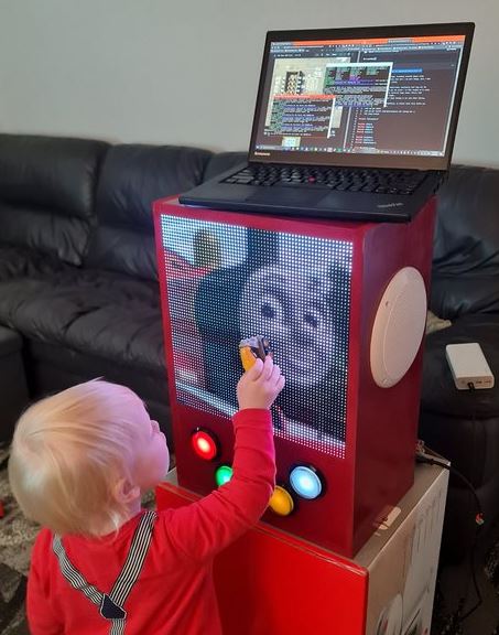
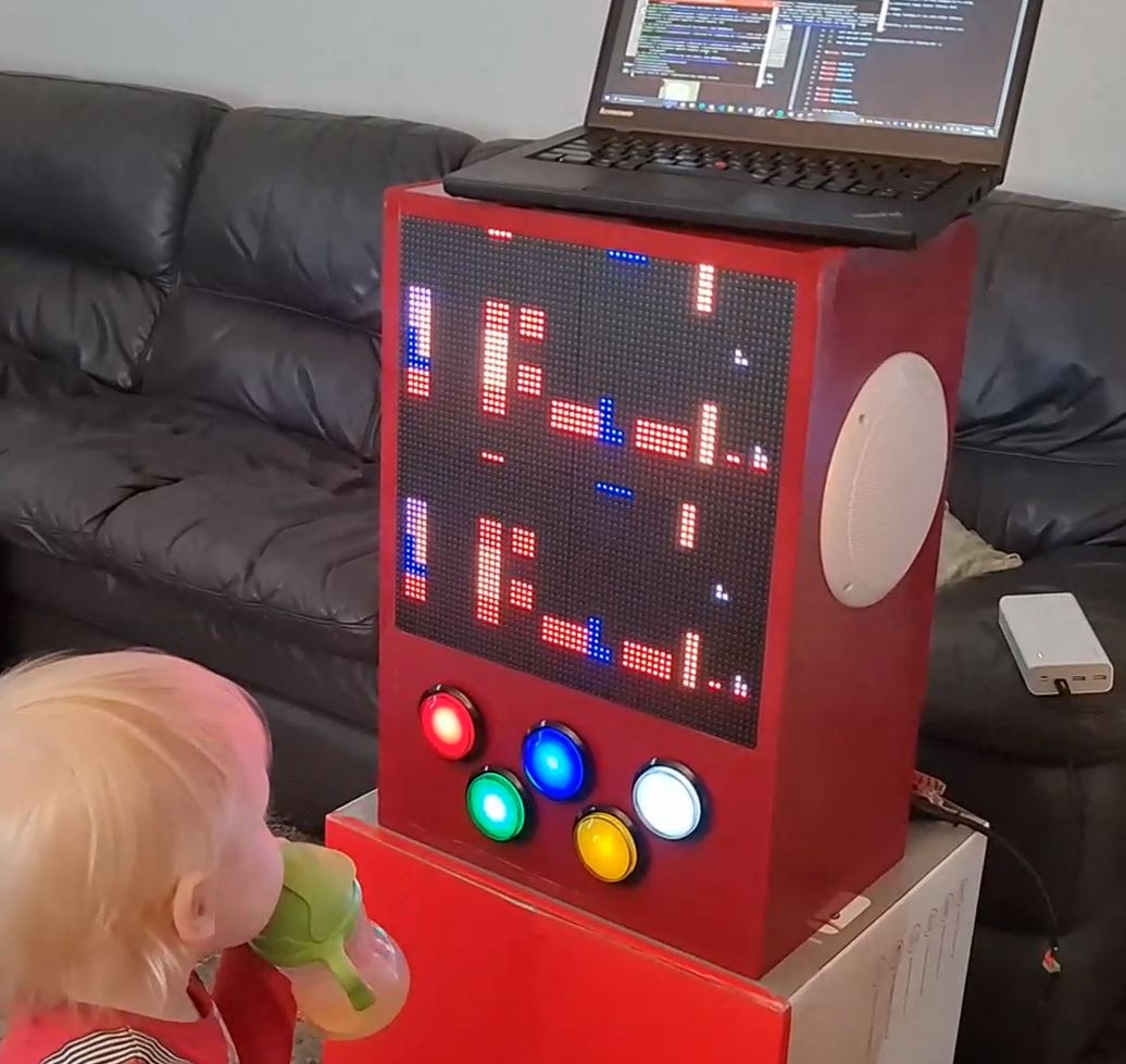
An Arcade Machine of Sorts
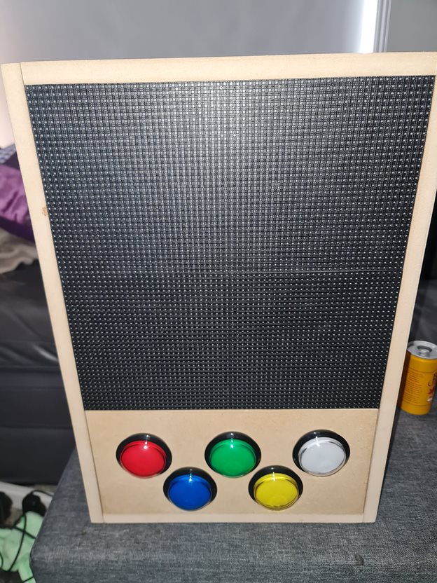
About a month ago, I posted about testing out a P5 Panel I'd acquired during an end of financial year sale from one of my go-to suppliers. This weekend, I've had a chance now to do something a little more permanent with those panels by building an arcade machine. As my son becomes a little more interactive with things, it'll be a fun way to program a few little games for him to muck about with.
The first step for this build was to pull out my trusty old version of Sketchup 2017 and draw out a basic frame. Inside of this, some 60mm illuminated buttons from Amazon, 2 x P5 Panels and 2 x 165mm marine speakers will need to fit into the chassis. I made sure to also include the width of the MDF when measuring out the box to ensure we're not the 40mm short for the speakers to comfortably sit.
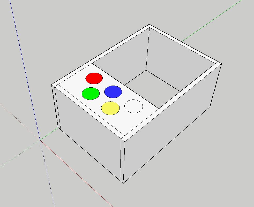
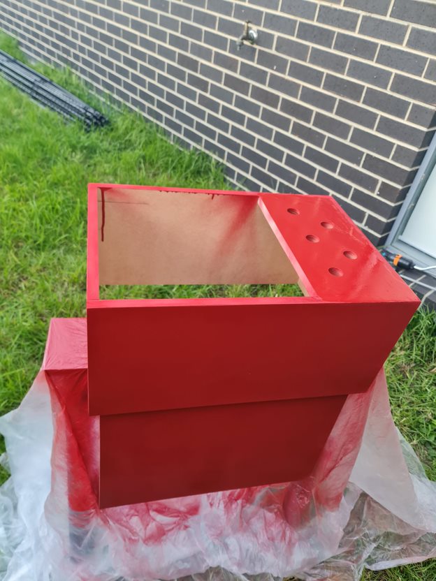
I've opted to go straight lines with this, we can use a routing bit or T-moulding to clean this up later - but otherwise straight lines are going to be infinitely easier to work with here, and will support some vertical mounting later. With each of these panels determined, it was time to go to Bunnings to find some suitable MDF. In this case, it won't be exposed to weather so the ease of working with MDF over Plywood was the deciding factor here, but you could quite easily go the Plywood route if you wanted something a little more solid. I got some 1200mm x 600mm x 16mm MDF (as T-moulding usually comes in 16mm), some red spray paint and got to work cutting the panels out.
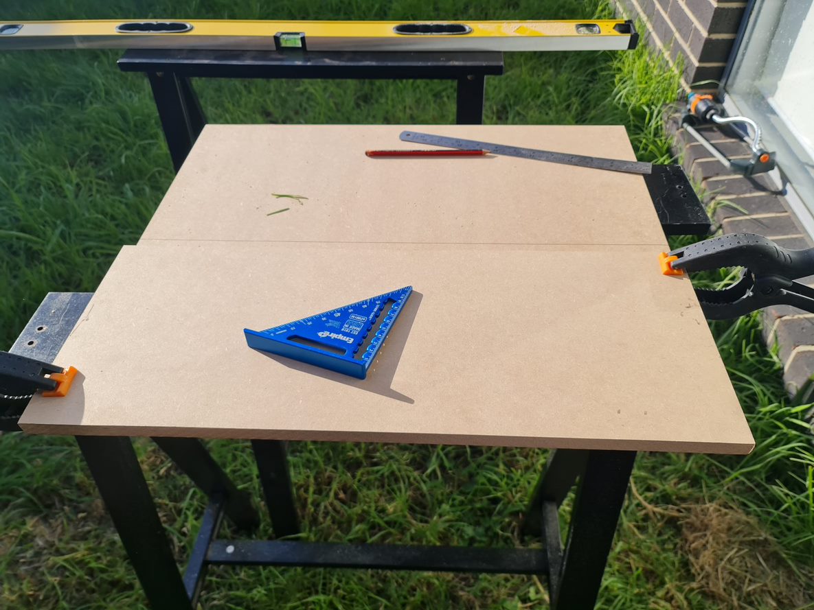
Yeah, that lawn really needs mowing - but given how wet it's been around here, it's been near impossible to find a good enough day that won't involve mud flinging from one side to the other. That aside, once it was all cut out and sanded back to the right size, some drilling + wood screws got the box assembled pretty easily. I used a hole saw bit with the drill to get the holes in for the arcade button - taking care to drill the pilot hole first, and cutting about 50% of the way in first before finishing from the other side. The advantage of doing this is you won't end up with any chipped wood as a result of the final bit being cut off (lesson learned from a previous arcade project!). All assembled to ensure things fit, it was time to get the wood filler to patch any holes before painting.
With the components all fitting nicely, it was time to print some joiners for the screens so that they line up as good as possible, while giving me something to screw into the chassis. Thankfully, someone had already designed some joiners so I didn't have to go out of my way to design them myself. With those on the printer, I had to make a door for the back and add some hinges. With that out of the way, it was time to paint. Now, I suck at painting - I can never get the right amount of spray paint on this. I was doing well until the final coat - but overall it's a nice colour - given my son's favourite colour right now is "James".
After a few coats of paint and an overnight dry, it was time to cut the holes for the speakers out by drawing a circle around 135mm diameter. Now, I don't have a protractor but I did have a ruler with a hole and a screw - so I was able to fashion something out of a ruler, marker and screw to draw a circle. With a large drill bit and a jig saw, the hole was in place and ready for installation.
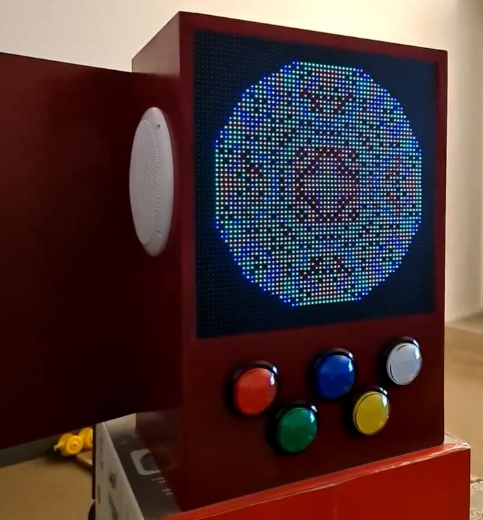
Ok! This is starting to look pretty cool, still need to wire up the buttons and speakers. To do the speakers, I'd ordered a super cheap 50W amplifier board from Amazon while waiting for some slightly better ones to come along. This would allow for the marine speakers to have enough 5V juice to make some noise. Despite some crackling, the speakers are pretty good for some cheapies from DJ City. They'll do for some outdoor speakers mounted inside some resin rocks I'm planning for later in the year! I won't link the amplifier here, but any TPA3116D2 based amplifier will work here. With that wired in, I had a few USB sound cards in use here for a Raspberry Pi Zero. As the P5 Panels need the hardware pulse that is normally reserved for audio (otherwise you get lots of flickering), it's not a problem to use whatever USB sound card you might have lying around. I guess you could use HDMI audio if you can get the right converter.
For the button wiring, I had been using the rPi-P10 controller from Hanson electronics. You can of course wire this in manually if only using one chain, but this board does include some level shifters (3.3V to 5V) that will come in handy shortly. Unfortunately, the use of the level shifters means we can't detect any button presses. After jumping on the soldering iron, I'd pulled out a small PCB, several terminal connectors, used a tall-header GPIO Pin Header (to allow hat stacking), and wired on some Dupont connectors for lighting up the LEDs for the buttons individually. In hindsight, I might have replaced the buttons with some WS2811 LEDs to control the colour as well, maybe a future project than the LEDs with resistor values for 5V.
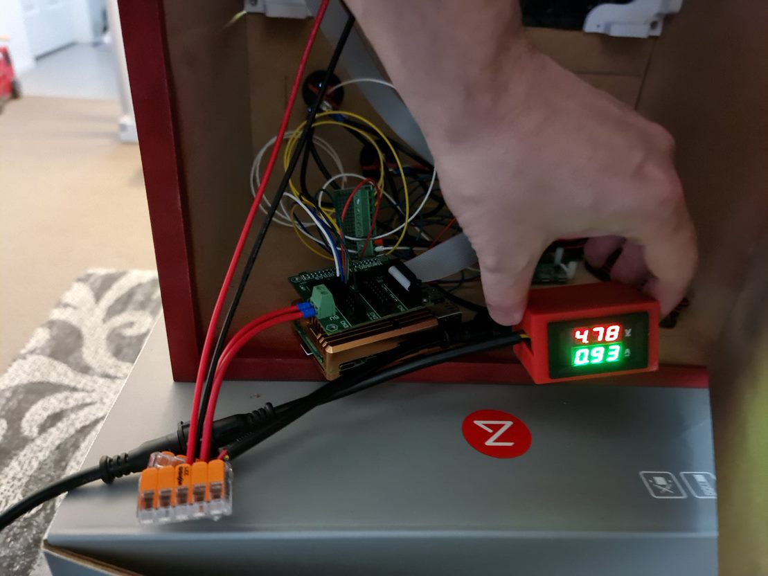
The rPi-P10 board is wired using this diagram - so reverse engineering it, I had determined I'll use the slots reserved for the second chain for the LED lights, and the third chain for buttons. I had confirmed the pinout works per the document before cutting away at pins. In the end, I had chopped 5 legs off the stacking connector so that they wouldn't pass through to the rPi-P10 hat for the buttons, and using Dupont connectors found the right R0/G0/B0/R1/B1 pins within the second connector so I could take advantage of the 5V level shifter on this board. You could simply use a level shifter and build your own board, but this crude board does the job for now. In the coming month, I'm going to give KiCad a go for this board and check out a process using JLCPCB or PCBWay to produce and send them through. It's so cheap these days to get custom PCBs, but it would have helped here to not have jump wires all over the board.
The final step was to wire it up, write some test code to ensure the buttons all work and to have some songs and pictures show up. Impressively, this set up under normal usage sits around 1A at 5V, so this whole thing is powered for several 10s of hours from a Romoss 30,000mAh battery. I had a Raspberry Pi 4 in at the time to do some debugging with (much faster to compile), but even that kept all lights lit and the matrix running at around that 1A mark (65% brightness). Obviously, the more white on the screen and loudness of the speakers all play a part, but impressive none-the-less.
Suffice to say as I sit here on a lazy Sunday afternoon, it looks pretty awesome and kiddo loves it too. Hopefully it'll give my phone five minutes of peace while we can code some things for it such as some low-res PICO-8 games that make use of the buttons.